Tutorial 1: Getting Started
This tutorial demonstrates how to use LoadPro for 2D structural analysis. Through this exercise, you will learn how to create a structural model, apply loads, and analyze beams, frames, and trusses using LoadPro.
Topics Covered
- Creating nodes and members
- Defining support conditions
- Applying loads
- Running analysis
- Viewing and interpreting results
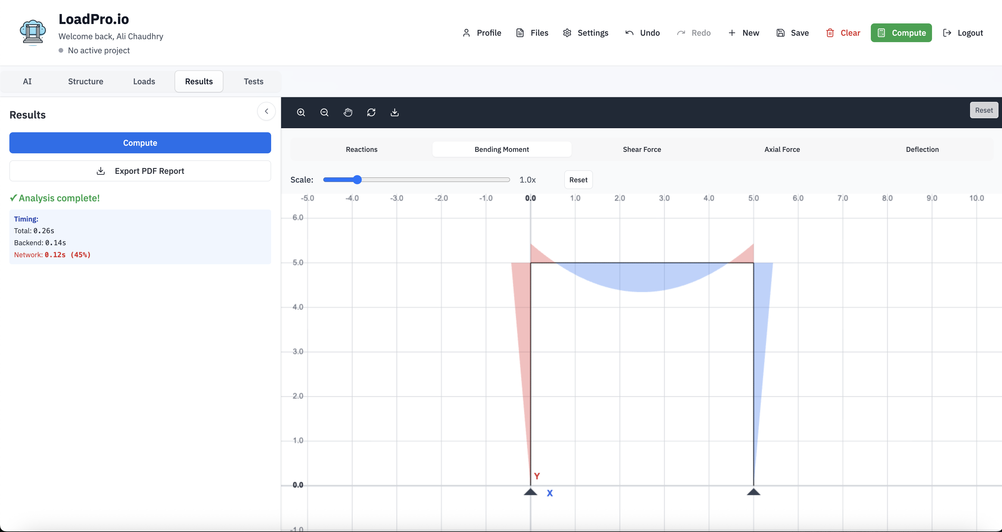
Figure 1: LoadPro interface overview
1. User Interface
LoadPro provides a clean, intuitive interface for structural analysis. The main workspace consists of:
- Canvas: The main drawing area where you build your structural model
- Sidebar: Contains tabs for nodes, members, loads, and results
- Toolbar: Quick access to analysis controls and view options
All analysis is performed directly in your browser—no installation or downloads required.
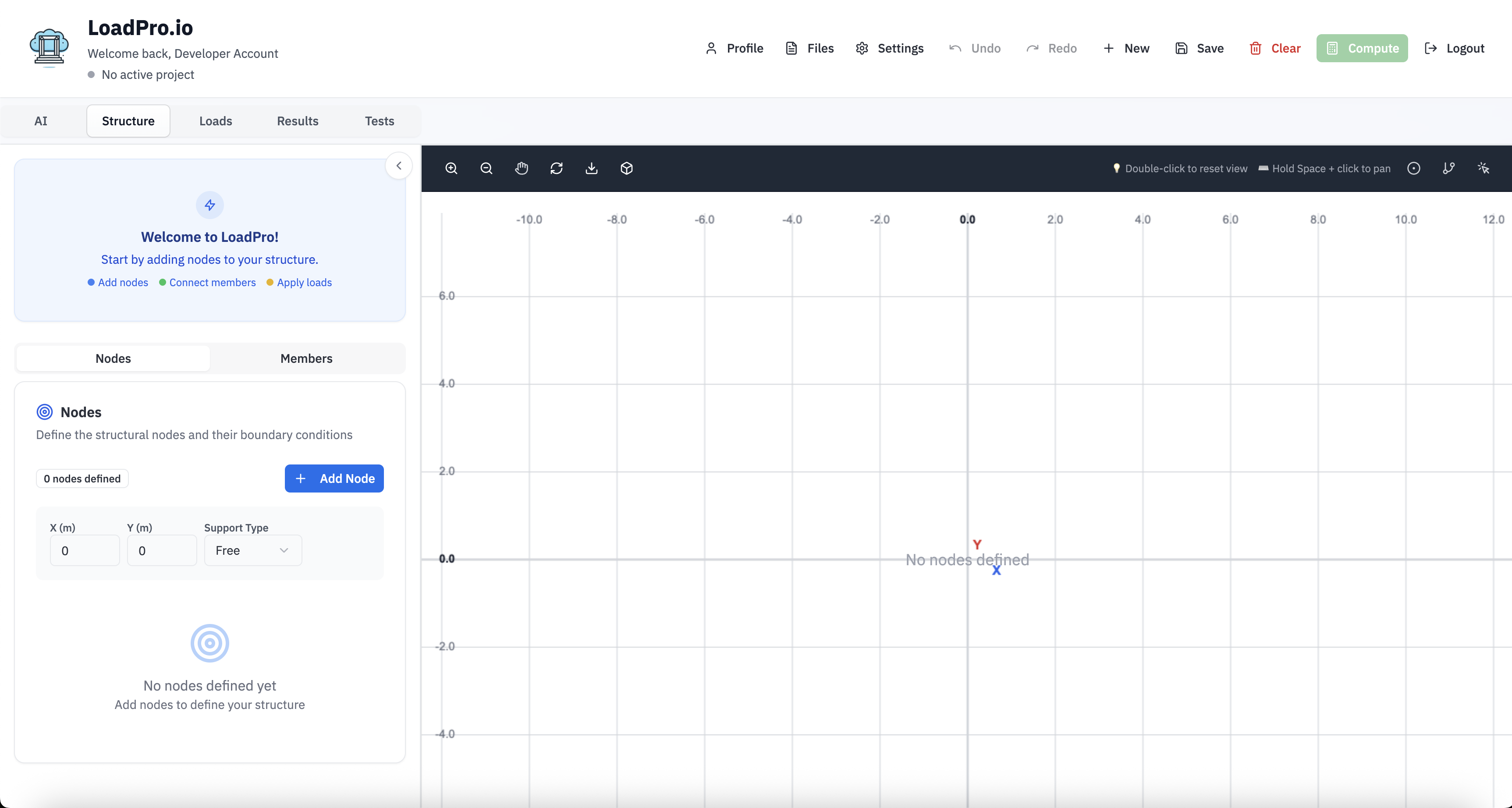
Figure 2: LoadPro workspace layout
2. Creating Your First Model
When you open LoadPro, you start with a blank canvas. Follow these steps to create your first structural model.
2.1 Adding Nodes
Nodes represent joints or connection points in your structure. There are two ways to add nodes:
Method 1: Using the Toolbar
- 1. Click the "Add Node" button in the canvas toolbar
- 2. Click anywhere on the canvas to place the node
- 3. Nodes are automatically numbered (1, 2, 3, etc.)
- Nodes are automatically numbered (1, 2, 3, etc.)
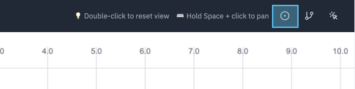
Figure 3a: Adding nodes using toolbar
Method 2: Using the Sidebar
- 1. Open the Nodes tab in the sidebar
- 2. Click "Add Node" or enter coordinates manually
- 3. The node will appear on the canvas at the specified location
- The node will appear on the canvas at the specified location
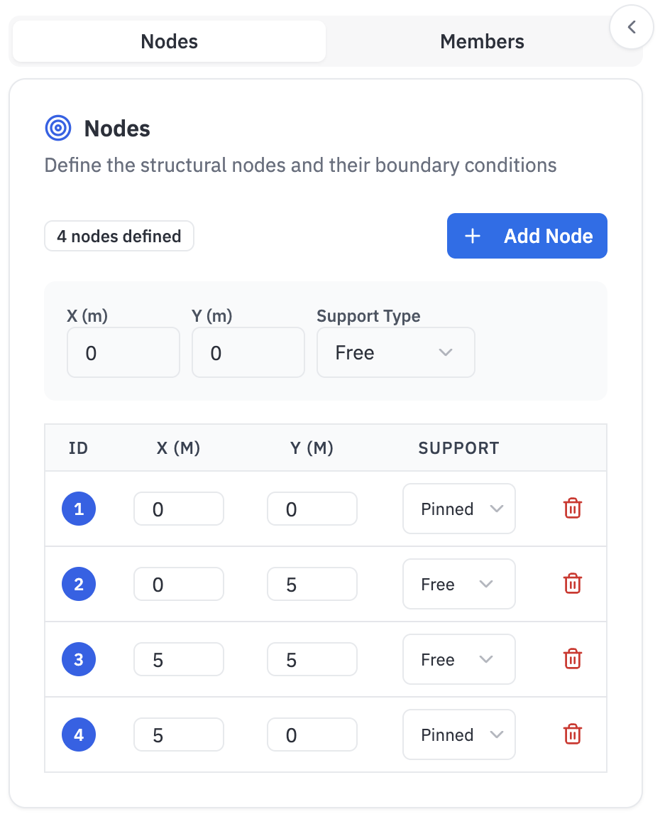
Figure 3b: Adding nodes using sidebar
Example Node Layout
Define the four base nodes using the coordinates below, then set supports as noted.
| Node | X (m) | Y (m) | Support |
|---|---|---|---|
| 1 | 0 | 0 | Pinned |
| 2 | 0 | 5 | Free |
| 3 | 5 | 5 | Free |
| 4 | 5 | 0 | Pinned |
Tip: You can move nodes by dragging them to new positions. Right-click on a node to delete it. For beam analysis, start with two nodes. For frame analysis, create nodes at all joints and corners.
2.2 Defining Supports
Supports define boundary conditions for your structure. LoadPro supports three types:
- Pinned: Prevents translation in X and Y directions (allows rotation).
- Roller: Prevents translation in Y direction only (allows horizontal movement and rotation).
- Fixed: Prevents translation and rotation (fully constrained).
There are two ways to define support conditions:
Method 1: Using the Sidebar
- 1. Select a node by clicking on it
- 2. In the sidebar, navigate to the node properties
- 3. Choose the support type (Pinned, Roller, or Fixed)
- 4. The support will be visually indicated on the canvas
- The support will be visually indicated on the canvas
Method 2: Right-Click Menu
- 1. Right-click on a node to open the context menu
- 2. Select "Set Support" from the menu
- 3. Choose the support type (Pinned, Roller, or Fixed)
- 4. The support will be visually indicated on the canvas
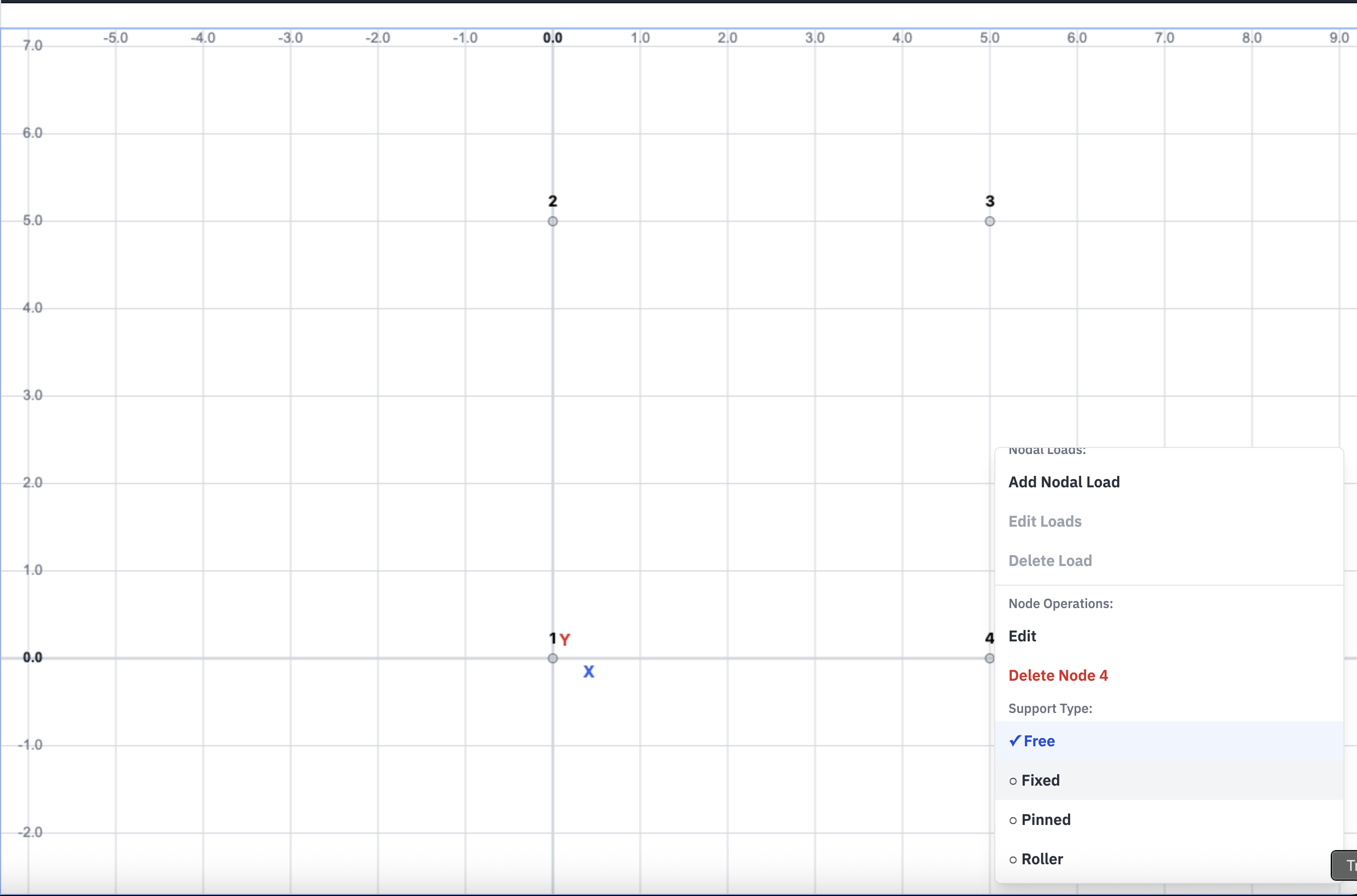
Figure 4: Setting support conditions via right-click
2.3 Adding Members
Members connect nodes to create structural elements (beams, columns, truss elements). There are two ways to add members:
Method 1: Using the Toolbar
- 1. Click the "Add Member" button in the canvas toolbar
- 2. Click and drag from one node to another to create a member
- 3. Members are automatically numbered
- Members are automatically numbered
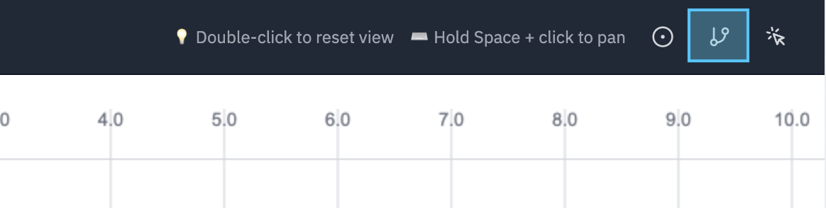
Figure 5a: Adding members using toolbar
Method 2: Using the Sidebar
- 1. Open the Members tab in the sidebar
- 2. Click "Add Member" and select start and end nodes
- 3. Or enter node IDs manually to connect them
- 4. Members are automatically numbered
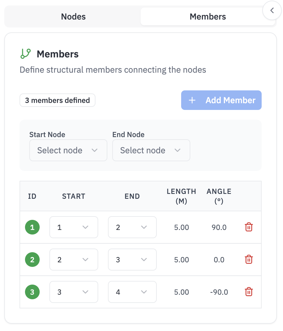
Figure 5b: Adding members using sidebar
Each member requires material properties:
- E (Elastic Modulus)
- I (Moment of Inertia)
- A (Cross-sectional Area)
2.4 Applying Loads
Loads can be applied to nodes (point loads) or members (distributed loads). LoadPro supports:
- Point Loads: Applied at nodes (forces in X, Y, or moments).
- Distributed Loads: Applied along members (uniformly distributed load per unit length).
- Concentrated Loads: Applied at specific positions along members.
There are two ways to apply loads:
Method 1: Using the Toolbar
- 1. Select a node or member on the canvas
- 2. Click the "Add Load" button in the toolbar
- 3. Enter the load magnitude and direction in the popup dialog
- 4. Loads are displayed as arrows on the canvas
- Loads are displayed as arrows on the canvas
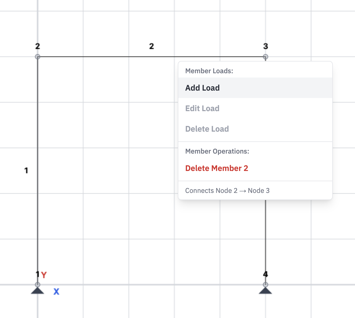
Figure 6a: Applying loads using toolbar
Method 2: Using the Sidebar
- Select a node or member
- Navigate to the Loads tab in the sidebar
- Click "Add Load" and specify the load type, magnitude, and direction
- Loads are displayed as arrows on the canvas
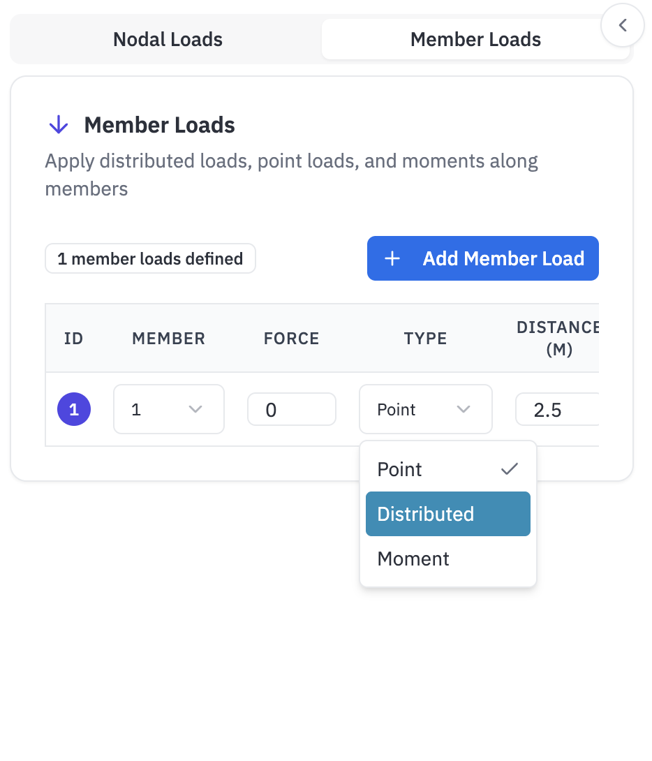
Figure 6b: Applying loads using sidebar
3. Running Analysis
Once your model is complete, you can run the structural analysis:
- Click the "Analyze" button in the toolbar.
- LoadPro will compute:
- Support reactions.
- Member forces (axial, shear, moment).
- Node displacements.
- Deflected shape.
- Analysis typically completes in less than 5 seconds.
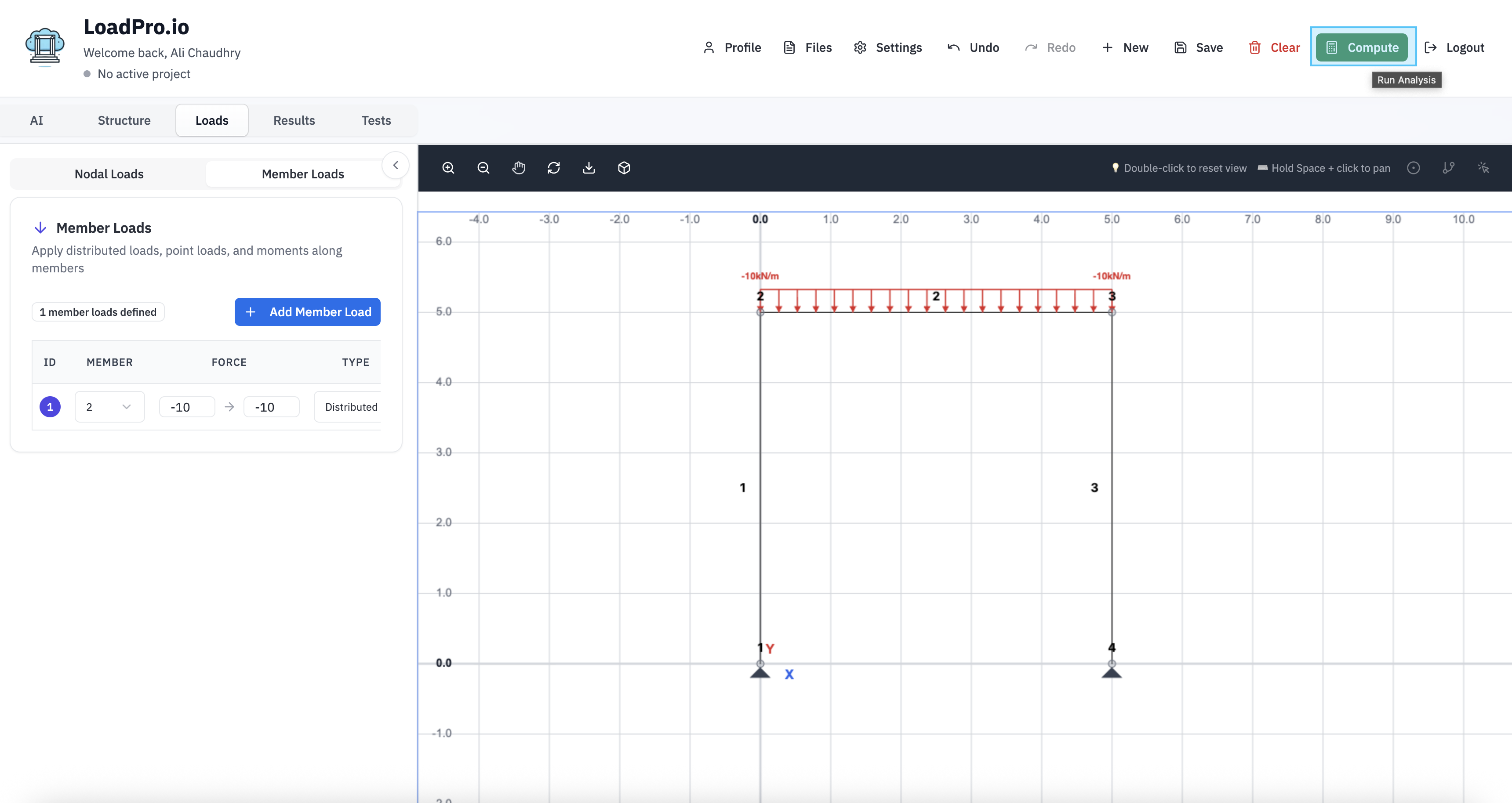
Figure 7: Running analysis in LoadPro
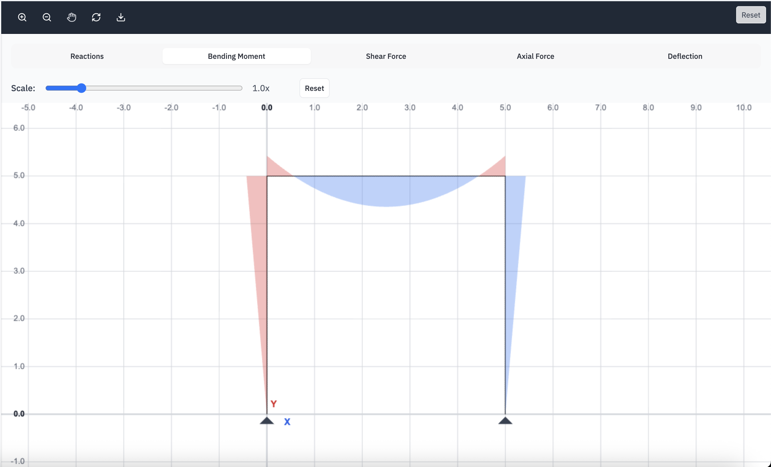
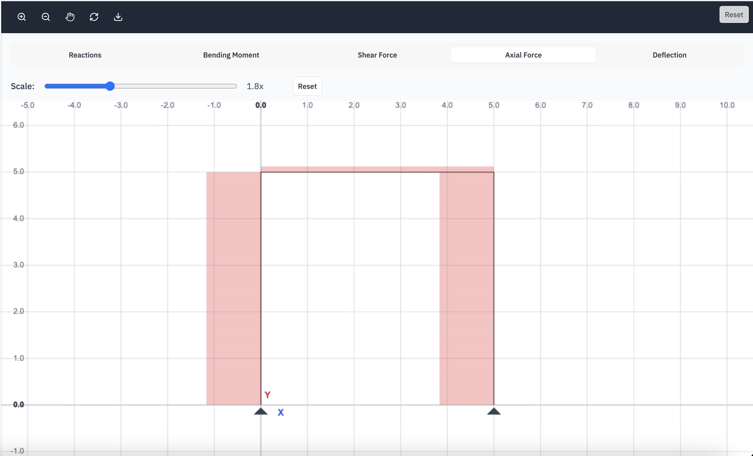
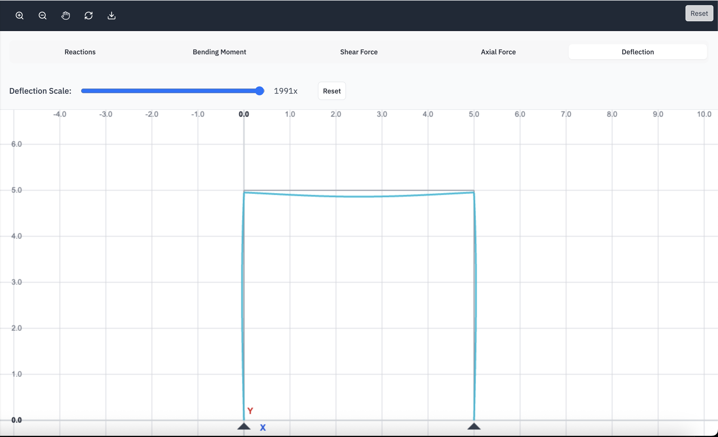
4. Viewing Results
After analysis, switch to the Results tab to view:
- Reactions: Forces and moments at supports.
- Moment Diagrams: Bending moment along each member.
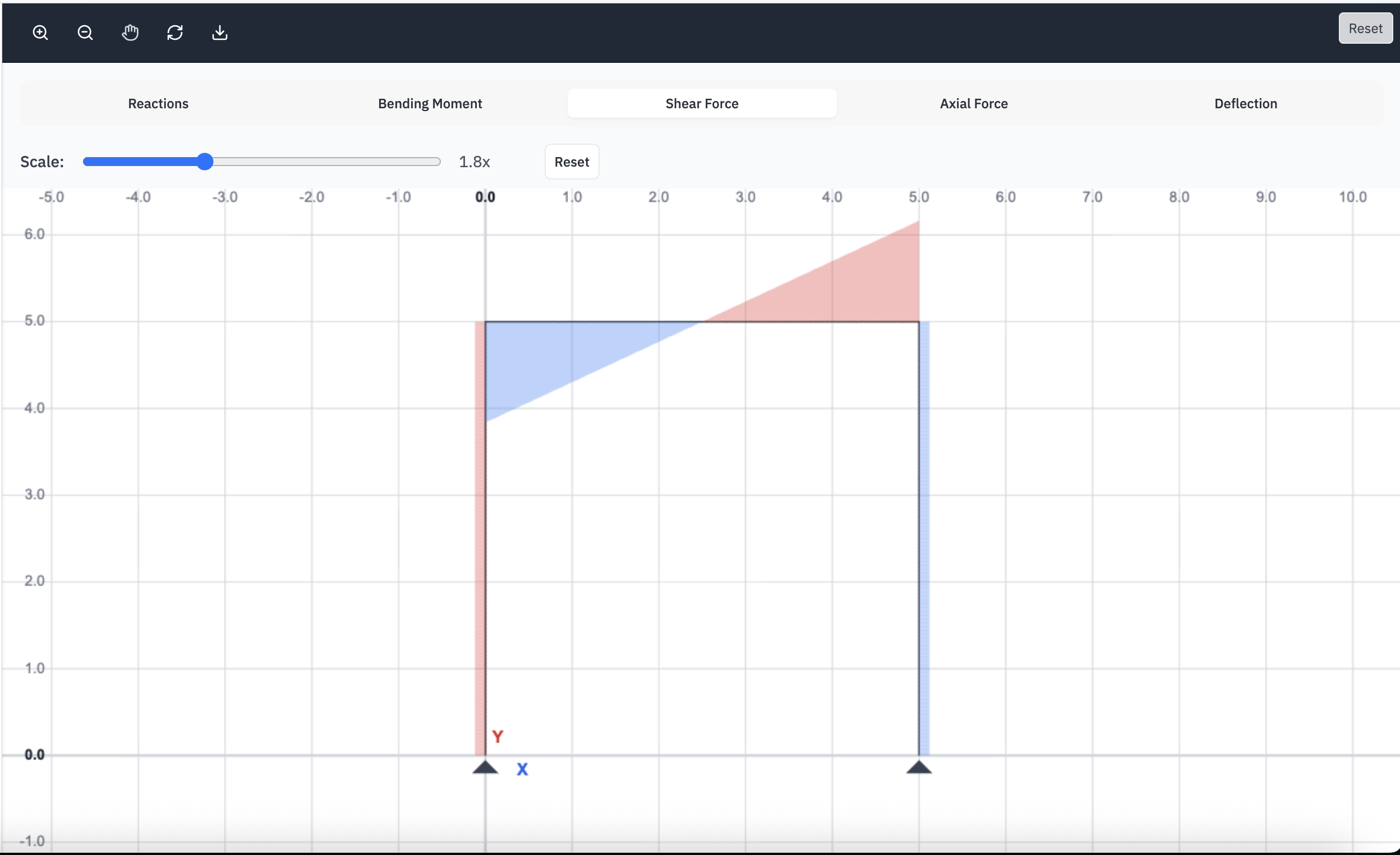
- Shear Diagrams: Shear force along each member.
- Axial Force: Axial force in each member.
- Deflected Shape: Visualization of structure deformation.
Use the toolbar controls to:
- Zoom in/out and pan the view.
- Toggle gridlines and labels.
- Adjust diagram scales for better visualization.
Figure 8: Results diagrams and visualizations
5. Exporting Results
LoadPro allows you to export your analysis results:
- PDF Export: Generate a professional report with diagrams and results.
- Save Project: Save your model for later use.
- Load Project: Open previously saved models.
PDF reports include diagrams, support reactions, and key results in a format suitable for documentation and submission.